6 Wire Thermostat Diagram

How To Wire 240v 230v Simultaneous Water Heater Thermostat In 2020 Water Heater Thermostat Water Heater Heater

5 Pin Bosch Relay Wiring Diagram Fitfathers Me Thermostat Wiring Electrical Wiring Diagram Electrical Circuit Diagram

Coleman Mach Rv Thermostat Wiring Free Download Wiring Diagram Schematic Thermostat Wiring Electric Motor Electricity
Search for 6 wire diagram for thermostat wire here and subscribe to this site 6 wire diagram for thermostat wire read more.

6 wire thermostat diagram. Heat pumps are different than air conditioners because a heat pump uses the process of refrigeration to heat and cool. You can find one online on a number of sites or you can check the manual that comes with your new thermostat. Six wire thermostats are typical with heating systems that have two stages of heat and one stage of air conditioning. Follow all safety precautions when doing electrical work.
Thermostat wiring diagrams for heat pumps heat pump thermostat wire diagrams. Rc red wire power 24 vac rh or 4 red wire jumpered power 24 vac w white wire for heating enable y yellow wire for cooling enable. Search for 6 wire thermostat nest here and subscribe to this site 6 wire thermostat nest read more. Color of wire and termination.
Before you hook up your thermostat its a good idea to check a six wire thermostat diagram. Find your 6 wire thermostat nest here for 6 wire thermostat nest and you can print out. Thermostat wiring for dummies. Find your 6 wire diagram for thermostat wire here for 6 wire diagram for thermostat wire and you can print out.
The basic heat ac system thermostat typically utilizes only 5 terminals. Attach the green wire to the g terminal to control the fan compressor. See the diagram below for what each wire controls on your system. The main trouble is dealing with those different colored wires knowing which one does what and if that wasnt enough you also have numbers and letters to deal with.
It is a red wire and comes from the transformer usually located in the air handler for split systems but you may find the transformer in the condensing unit. The thermostat uses 1 wire to control each of your hvac systems primary functions such as heating cooling fan etc. S indoor and outdoor wired sensors y compressor stage 1 cooling y2 compressor stage 2 cooling g fan c common u humidifier dehumidifier or ventilator control la a input. Heck now im not calling anyone a dummy.
While an air conditioner uses the process of refrigeration to only cool the central air conditioner will usually be paired with a gas furnace an electric furnace or some other method of heating. Thermostat wiring and wire color chart thermostat wiring colors code. Most models follow a thermostat color code for ease of use key in telling you which wires to connect to which terminals. For this reason.
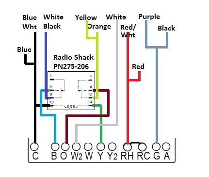
6 wire thermostat diagram wiring diagram is a simplified agreeable pictorial representation of an electrical circuitit shows the components of the circuit as simplified shapes and the gift and signal connections amid the devices. A wiring diagram usually gives counsel very nearly the relative twist and understanding of devices and terminals upon the devices to back in building or. The diagram below shows how a basic 4 wire thermostat is connected as indicated by the color code chart above. The white wire connects to the w terminal and controls the heat and the yellow wire which connects to the y terminal controls cooling.
R the r terminal is the power. One of the biggest complaints or rather reasons for.

Thermostat Simultan Wir Di Diagram Kabel Untuk Air Panas Rheem Panas

Wiring Diagram For 220 Volt Submersible Pump Submersible Well Pump Well Pump Submersible Pump
107 Best Eddy Images House Wiring Thermostat Wiring Electrical Wiring Diagram

22 Clever Car Wiring Diagrams Explained Design Https Bacamajalah Com 22 Clever Car Wiring Diagrams Ex Electrical Circuit Diagram Diagram Electrical Diagram

Trane Thermostat Wiring Diagram Luxury Wiring Diagram For Trane With Regard To Trane Wiring Diagram Trane Heat Pump Thermostat Wiring Trane

Refrigerator Thermostat Connection And Full Electric Wiring Refrigerator Diagram With Practical In 2020

Add Another Thermostat To Gas Or Electric Heater Electric Water Heater Heater Electricity

Heat Wiring An Spdt Thermostat To Simultaneously Control Heating Band Heater Wiring Diagram At Elf Jo Com Thermostat Wiring Heating Thermostat Thermostat

Fresh Megaflo Wiring Diagram Y Plan Diagrams Digramssample Diagramimages Wiringdiagramsample Wiringdiag Heating Systems How To Plan Central Heating System
